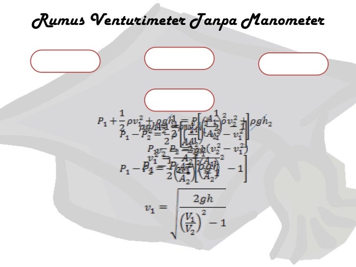
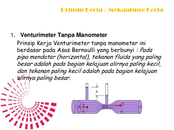
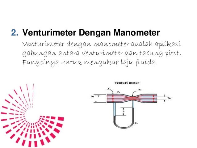
- Rumus Venturimeter Dengan Manometer
- Penurunan Rumus Venturimeter Tanpa Manometer
- Turunan Rumus Venturimeter
- Rumus Tabung Venturimeter
- Rumus Venturi Meter
Venturi meters are flow measurement instruments which use a converging section of pipe to give an increase in the flow velocity and a corresponding pressure drop from which the flowrate can be deduced. They have been in common use for many years, especially in the water supply industry.
Venturi Meter is a device in which pressure energy is converted into kinetic energy and it is used for measuring the rate of flow of liquid through pipes. It is invented by an American Engineer Clemans Herchel and named by the Italian physicist Giovanni Venturi. It works on the basic principle of Bernoulli's Equation. Parts of Venturi Meter. Efek venturi adalah suatu penurunan dari tekanan fluida yang terjadi ketika fluida tersebut bergerak melalui suatu pipa yang menyempit. Efek tersebut pertama kali ditemukan oleh Giovanni Battista Venturi pada abad ke-19.
The classical Venturi meter, whose use is described in ISO 5167-1: 1991, has the form shown in Figure 1
Figure 1. Classical Vetituri meter design. (From B. S. 7405 (1991) Fig. 3.1.4, with permission of B.S.I.)
For incompressible flow if the Bernoulli Equation is applied between two planes of the tappings,

where p, ρ and ū are the pressure, density and mean velocity and the subscripts 1 and 2 refer to the upstream and downstream (throat) tapping planes.
From continuity
whereis the volumetric flowrate and D and d the pipe and throat diameters.

Combining Eqs. (1) and (2)
where β is the diameter ratio, d/D. In reality, there is a small loss of total pressure, and the equation is multiplied by the discharge coefficient, C, to take this into account:
where Δp is the differential pressure (≡p1 − p2). The discharge coefficient of a Venturi meter is typically 0.985, but may be even higher if the convergent section is machined. Discharge coefficients for uncalibrated Venturi meters, together with corresponding uncertainties, are given in ISO 5167-1: 1991.
If the fluid being metered is compressible, there will be a change in density when the pressure changes from p1 to p2 on passing through the contraction. As the pressure changes quickly, it is assumed that no heat transfer occurs and because no work is done by or on the fluid, the expansion is isentropic. The expansion is almost entirely longitudinal and an expansibility factor, ε, can be calculated assuming one-dimensional flow of an ideal gas:
where τ is the pressure ratio, p2/p1, and κ the isentropic exponent. The expansibility factor is applied to the flow equation in the same way as the discharge coefficient.
Various forms of construction of a Venturi meter are employed, depending on size, but all are considerably more expensive than the orifice plate. However, because most of the differential pressure is recovered by means of the divergent outlet section, the Venturi causes less overall pressure loss in a system and thus saves energy: the overall pressure loss is generally between 5 and 20 per cent of the measured differential pressure. The Venturi meter has an advantage over the orifice plate in that it does not have a sharp edge which can become rounded; however, the Venturi meter is more susceptible to errors due to burrs or deposits round the downstream (throat) tapping.
The lengths of straight pipe required upstream and downstream of a Venturi meter for accurate flow measurement are given in ISO 5167-1: 1991. These are shorter than those required for an orifice plate by a factor which can be as large as 9. However, Kochen et al. show that the minimum straight lengths between a single upstream 90° bend and a Venturi meter in the Standard are too short by a factor of about 3.
REFERENCES
British Standards Institution (1991) Guide to selection and application of flowmeters for the measurement of fluid flow in closed conduits, BS 7405.
International Organization for Standardization, Measurement of fluid flow by means of pressure differential devices—Part 1: Orifice plates, nozzles and Venturi tubes inserted in circular cross-section conduits running full. ISO 5167-1: 1991.
Kochen, G., Smith, D. J. M., and Umbach, A. (1989) Installation effects on Venturi tube flowmeters, Intech Engineers Notebook, October 1989,41-43.
References
- British Standards Institution (1991) Guide to selection and application of flowmeters for the measurement of fluid flow in closed conduits, BS 7405.
- International Organization for Standardization, Measurement of fluid flow by means of pressure differential devices—Part 1: Orifice plates, nozzles and Venturi tubes inserted in circular cross-section conduits running full. ISO 5167-1: 1991.
- Kochen, G., Smith, D. J. M., and Umbach, A. (1989) Installation effects on Venturi tube flowmeters, Intech Engineers Notebook, October 1989,41-43.
What is venturimeter:-
“It is a device used to measure the speed and flow rate or discharge of fluid through a pipe.” Venturimeter is work on Bernoulli’s equation.
Its basic principle also depend on Bernoulli’s equation and continuity equation. Velocity increases pressure decreases.
Simple meaning is “When cross sectional area of the flow is reduces it creates pressure difference between the different areas of flow. This difference in pressure is measured with the help of manometer and helps in determining rate of fluid flow or other discharge from the pipe line.”
History:- The principle of venture meter is firstly developed by G.B. Venturi in 1797 but this principle comes into consideration with the help of C. Herschel in 1887.
Main parts of Venturimeter:-
Rumus Venturimeter Dengan Manometer
1. Converging part

2. Throat
3. Diverging Part
Converging part
It is starting section of venturimeter which attached at inlet pipe. The cross sectional area of this cone starts to decrease and the converging angle is 20 degree. Its length is 2.7(D-d). Here (D) is the diameter of inlet section and (d) is the diameter of throat. Other end of converging is attached with throat.
Throat
Throat is middle portion of venturimeter and its cross sectional area is too small. At this point pressure is decreases and velocity is increases. One end is connected with converging part and other end is attached with diverging part. Diameter of throat is ¼ to ¾ of the diameter of the inlet pipe, but mostly it is ½ of the diameter of the pipe.
Diverging part
Diverging part is last part of venturimeter and its cross sectional area is increases continually. Angle of diverging part is 5 to 15 degree. Its cross sectional area continuously increases. One end is connected to throat and other end is connected to outlet pipe.The main reason behind the low diverging angle is to avoid the formation of eddies because flow separation and eddies formation will results in large amount of loss in energy
Working:-
· Venturimeter is work on Bernoulli’s equation and its simple principle is when velocity increases pressure decreases.

· Cross sectional area of throat section is smaller than inlet section due to this the velocity of flow at throat section is higher than velocity at inlet section, this happen according to continuity equation.
· The increases in velocity at the throat result in decreases in pressure at this section , due to this pressure difference is developed between inlet valve and throat of the venturimeter.
· This difference in pressure is measured by manometer by placing this between the inlet section and throat.
· Using pressure difference value we can easily calculate flow rate through the pipe.
Expression for the rate of flow through venturimeter:-
Let d1, p1, v1 & a1, are the diameter at the inlet, pressure at the inlet, velocity at the inlet and area at the cross section 1.
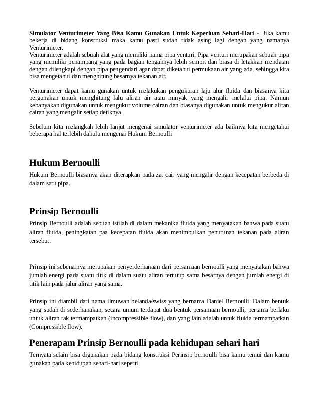
Penurunan Rumus Venturimeter Tanpa Manometer
And d2, p2, v2 and a2 are the corresponding values at section 2.
Applying bernoulli’s equation at sections 1 and 2
As the pipe is horizontal, so z1 = z2
Therefore
(P1 – P2)/ρg is the difference of pressure heads at section 1 and 2 and it is equal to h. so
Substituting this value of h in equation (1), we get
Now applying continuity equation at section 1 and 2
Substituting this value of v1 in equation (2) and solving, we get
Discharge
Turunan Rumus Venturimeter
Substituting value of v2 in above equation
Q is the theoretical discharge under ideal conditions. Actual discharge will be less than the theoretical discharge. The actual discharge is given by the formula
Rumus Tabung Venturimeter
Where Cd is the coefficient of venturimeter and its value is less than 1.
Rumus Venturi Meter
Author:-
Gopinath Murthi
